
7 Artificial lighting
Interiors and exteriors
Within buildings, where there is insufficient daylight, there is a need for artificial lighting whilst occupants are present, so that they can perform their tasks, with the amount and quality of illumination provided depending upon the nature of those tasks. Work that requires fine discrimination of visual detail may need higher lighting levels than say walking through a corridor or watching a television, which acts as its own source of illumination. This artificial lighting may be provided in the form of general background lighting (e.g. downlighting from or uplighting to a ceiling) local task lighting (e.g. desk lamps) or a combination. This lighting may be manually controlled, automatically controlled, or a hybrid with occupants being able to override automated controls. This control may respond to presence detectors or daylight availability and may also be used to adjust the mood (the amount and quality) of lighting, depending upon the time of day or the tasks being performed. The degree of control that is possible can also vary, depending upon the nature of the lamps that are used within a luminaire (the light fitting). This chapter addresses these issues and explains how lighting layouts can be dimensioned to meet occupants’ needs.
7.1 Visual perception, illumination levels and comfort
The spectral sensitivity of the human eye was introduced in brief in Chapter 6, in the context of daylighting in architecture. This was brief, in part because there are somewhat limited opportunities to control the spectral (wavelength dependent) composition of daylight which reaches the eye: the light source (the spectral composition of terrestrial daylight) is fixed, but we can modify this composition through transmission and reflection. In artificial lighting we have all three degrees of freedom: the light source and modifications through transmission and reflection, as well as how artificial light can be combined with natural daylight. It seems suitable then to delve a little deeper now into the functioning of the human eye and how we humans perceive light and colour.
Perception
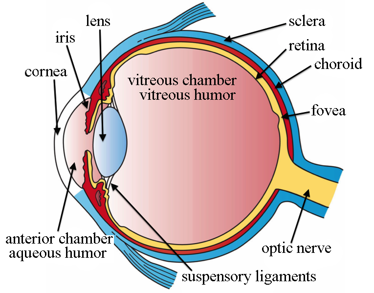
The human eye may be thought of as a complex optical device. Light first passes through an outer lens (the cornea), en-route to an aperture (the pupil) that is located in a diaphragm (the coloured part of the eye – the iris) which controls the amount of light that enters the interior of the eye – this being wide open under low light conditions. The light then passes through another lens which focuses the light onto the retina, which contains photoreceptor cells that contain photoreceptive proteins that absorb light, triggering electrical signals that are transmitted through the optic nerve to the brain. There are three types of photoreceptive cells: rods, cones and intrinsically photosensitive retinal ganglion cells.
Rods primarily mediate scotopic vision, which relates to dim (e.g. night time) conditions and cones mediate primarily photopic vision (bright conditions). The retinal ganglion cells do not contribute towards sight, but they do play an important role in regulating our circadian rhythm; our so-called biological clock.
There are three types of cone cell, each having a different spectral sensitivity. These are normally designated as L, M and S corresponding long, medium and shortwave wavelength sensitivity respectively. The S-cone has a peak sensitivity at 420nm, so it is more likely to absorb a photon at this blue-biased wavelength (and transmit a corresponding electrical signal) than any other. The cones cannot measure wavelengths directly, but the ratio of the responses from the three cone types can indicate the wavelength and thus enable colour vision. In contrast, there is only one type of rod cell, with a peak sensitivity at 498nm, so we humans are poor at discriminating between colours at low light levels (scotopic vision).
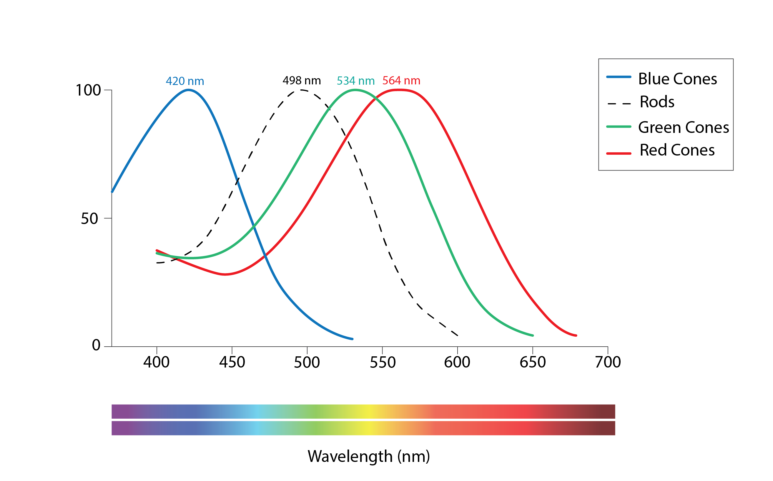
If two monochromatic light sources of 564nm (red) and 534nm (green) illuminate a white surface, the eye will not separate them. They will appear as an additive mix of the two colours, in this case as the secondary colour, yellow (as indicated in the Venn diagram below). Similarly, if red, green and blue light sources of uniform intensity are combined, the eye will perceive the resultant colour to be white (the centre of the Venn diagram). This is the basis for stage lighting, as well as for computer monitors and television screens. These latter are comprised of small R, G, B pixels, which the eye perceives as a macroscopic combination of the individual component parts based on their relative proportions. Indeed, we are able in this way to discriminate between 256 combinations of R, G and B, which combine to create >16 million (2563) distinct colours [1].
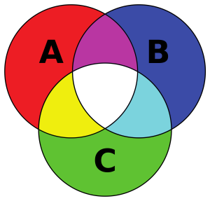
If the white light at the centre of the above Venn diagram passes through a red stained glass window (effectively, through a red filter), then only the red component will be transmitted, with the blue and green components being subtracted. Similarly, if white light is reflected from a surface that is painted red, then only the red component will be reflected, with the blue and green components again being absorbed.
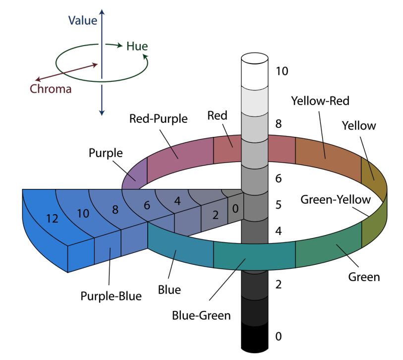
An alternative to this R, G, B colour model, is the Munsell colour system, proposed by the American artist Albert Munsell at the beginning of the 20th century. There are three component parts to this system: Hue, Chroma and Value. Hue is comprised of 5 principal colour hues (Purple, Red, Yellow, Green and Blue) and a further 5 intermediate hues (see the image below), each of these 10 being sub-divided into further /sub-hues, so that there are 100 integer values in total (though colour charts typically use only 40). Value (or lightness) varies vertically from 0 (black) to 10 (white). Chroma, measured radially in divisions of 2 from the centre of each slice, represents the purity of the colour, with low Chroma values being relatively impure, such as a pastel, and high values being relatively vivid. The Munsell system is commonly employed by artists in the specification of paints.
In addition to being able to discriminate between a vast array of colours, the eye is also able to perceive a vast range of illuminances, indeed spanning a range of  lux; detecting white objects under starlight (
 lux) and able to read text at illuminances 1000 times greater than that due to direct sunlight (
 lux).
lux).
| Lighting condition | Illuminance, lux (approx.) |
| Sunlight | 100,000 |
| Full daylight | 10,000 |
| Overcast day | 1000 |
| Dark day | 100 |
| Twilight | 10 |
| Full moon | 0.1 |
| Starlight | 0.001 |
The level of illumination that we need depends to a large extent on the tasks that we would like to perform. These tasks may vary in the extent of visual acuity demanded of the observer as well as in the contrast between the objects being observed and their background.
Visual acuity relates to a person’s ability to recognise small details with precision. Acuity depends upon both optical and neural factors. The former relates to the sharpness of the image that is projected onto the retina and the latter to the effectiveness with which this information is recognised, transmitted to and interpreted by the brain. Optical causes of low visual acuity include myopia (near-sightedness) and hyperopia (far-sightedness), which are caused by the focal point of the lens appearing before or after the lens respectively. Both cases tend to be exacerbated by aging which impairs the refractive power of the cornea and the lens. This of course can be compensated for with the use of eyeglasses or contact lenses. The sharpest and most brilliantly coloured vision occurs when images are focussed onto the fovea centralis – located above the optic nerve in figure 1 above – which is comprised of exclusively cone photoreceptor cells that are densely packed. Since photopic (cone-based) vision is activated at higher levels of illumination, it follows that visual acuity is enhanced at higher illuminance levels.
Visual contrast relates to the difference in brightness (luminance) between the object being observed and the background against which it is positioned. Discrimination of detail is enhanced at higher contrasts: the ratio of the luminance of the object under observation and that of its background. This is why text is typically printed in a black font appearing against a (near) white background. This contrast is more apparent when the printed page is exposed to higher levels of illumination (or at higher levels of brightness on a backlit screen).
Illumination types and levels
As indicated in the table below, taken from Volume A of the Chartered Institution of Building Services Engineers (CIBSE) Guide, high levels of maintained illuminance are required for tasks requiring fine discrimination of detail and/or circumstances in which the contrast between an object under observation and its background are low. The 2000 Lux case relates to details so small that they subtend less than 1 minute (1/60 of a degree) of arc.
| Standard illuminance, lux | Characteristics of activity / interior | Representative activities / interiors |
| 50 | Interiors used rarely, with visual tasks confined to movement and casual seeing without perception of detail |
Cable tunnels, indoor storage tanks, walkways |
| 100 | Interiors used occasionally, with visual tasks confined to movement, and casual seeing calling for only limited perception of detail | Corridors, changing rooms, bulk stores, auditoria |
| 150 | Interiors used occasionally, with visual tasks requiring some perception of detail or involving some risk to people, plant or product | Loading bays, medical stores, switch rooms, plant rooms |
| 200 | Continuously occupied interiors, visual tasks not requiring perception of detail | Foyers and entrances, monitoring automatic processes, dining rooms |
| 300 | Continuously occupied interiors, visual tasks moderately easy: large details and/or high contrast | Libraries, sports and assembly halls, teaching spaces, lecture theatres |
| 500 | Visual tasks moderately difficult, i.e. details to be seen are of moderate size (5–10 min. arc) and may be of low contrast; also colour judgement may be required | General offices, engine assembly, painting and spraying, kitchens, laboratories, retail shops |
| 750 | Visual tasks difficult, i.e. details to be seen are small and of low contrast; also good colour judgements may be required |
Ceramic decoration, meat inspection, chain stores |
| 1000 | Visual tasks very difficult, i.e. details to be seen are very small and can be of very low contrast; also accurate colour judgements may be required |
General inspection, electronic assembly, gauge and tool rooms, retouching paintwork, cabinet making |
| 1500 | Visual tasks extremely difficult, i.e. details to be seen extremely small and of low contrast; visual aids and local lighting may be of advantage |
Fine work and inspection, hand tailoring, precision assembly |
| 2000 | Visual tasks exceptionally difficult, i.e. details to be seen exceptionally small with very low contrasts; visual aids and local lighting will be of advantage | Assembly of minute mechanisms, finished fabric inspection |
This illumination may be provided through background lighting, task lighting or a combination of the two. Background lighting is typically provided by one or more luminaires fitted into or suspended from a ceiling, whereas task lighting is locally positioned to directly illuminate the objects that are the focus of a given task. For example, the assembly of electronic components is likely to involve a combination of both background and task lighting, to reduce the use of energy. The CIBSE (Guide A) recommends that under such circumstances an illuminance ratio of 3:1 should not be exceeded, to reduce the effort on the eye as the iris adjusts to the imaging of background (low brightness, larger aperture) and foreground (higher brightness, smaller aperture) objects.
Visual (dis-) comfort
Artificial lighting installations are, of course, not designed solely to support visual performance; the ability to conduct tasks and to support wayfinding internally and externally. Lighting design should also promote visual comfort, wellbeing and productivity. Indeed, good lighting design can instil a sense of joyfulness in the observer by accentuating through magnitude, spatiotemporal variation and colour objects and artefacts that the designer considers to be particularly pleasing. This is particularly the case in the daylighting and artificial lighting design of art galleries and museums.
In contrast, poorly designed lighting installations can also provoke visual discomfort. This can arise when the luminance (or brightness) levels are excessive, when the contrast in luminances is too high, causing fatigue due to frequent eye adaptation and conversely also when luminance levels and contrasts are too low resulting in a dull and un-stimulating visual field. As noted in the previous chapter on daylighting, the luminance of a surface L is a function of the incident illuminance, E and its reflectance  (in the case of a Lambertian reflector), so that
  [2].
[2].
Recommended illuminance levels for a range of different tasks were presented in the previous section, but to maintain comfort the spatial variation of illuminance should also be contained within a reasonable range, depending upon: (i) the task area, (ii) the immediate surrounding area, within a diameter of 0.5, of the task area, and (iii) the background area that lies within a 3m diameter of the task area. This variation is quantified by an illuminance uniformity ratio  , the ratio of the minimum illuminance
  to the average illuminance
  within the region of interest, so that
The SLL (2022) recommends that the illuminance uniformity ratio within the background and immediate surrounding area be  and
and  respectively.
In addition to ensuring that illuminance levels are of sufficient magnitude and a comfortable uniformity, lighting designers should also strive to ensure that occupants do not experience discomfort from glare (potentially also temporary impairments to vision), due to excess brightness or brightness variation of interior surfaces, visible parts of luminaires or other sources of illumination such as windows or rooflights. For example, when gazing through a window or rooflight, the sun may be visible and this may provoke impair vision, but this can be avoided by shifting one’s gaze away or by lowering blinds; this latter potentially causing a compensatory increase in light output from artificial lights, if linked with automated photoresponsive controls (of which more in s7.4).
The Commission Internationale d’Eclairage (CIE) has developed a Unified Glare Rating  with which to evaluate whether discomfort glare is likely to arise from a luminaire of a lighting installation. This can be calculated as follows:
(1) 
in which  is the background luminance, L is the luminance of luminous parts of the luminaire as seen from the observer’s eye, each subtending a distinct solid angle
  and p is a Guth position index for each luminaire, which relates to its displacement from the line of sight. In practice, the evaluation of is somewhat specialised and is normally carried out by luminaire manufacturers and reported in photometric data sheets.
7.2 Lighting technology
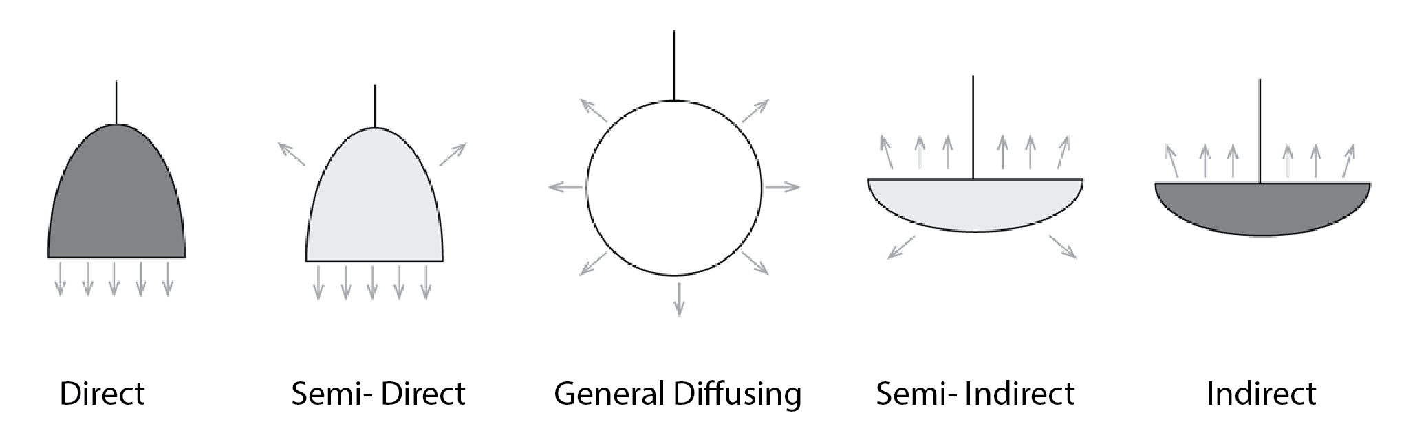
Luminaires are the fittings that accommodate one or more lamps and, in some cases, their reflectors. These fittings may be comprised of opaque, translucent or transparent materials. In the case of opaque materials, the luminous flux from the luminaire is either directed directly towards the focus of the task in hand, normally referred to as the working plane (typically at a height of 0.8m above the floor level), or indirectly following reflection from the walls or ceiling. In the case of transparent or translucent materials, a portion of the luminous flux emitted by the lamp is transmitted through the fitting, so that the luminaire is considered to be semi-direct or semi-indirect. In the case of a lamp that is fully housed within a translucent fitting, the luminaire is referred to as general diffusing. Direct luminaires tend to have a far greater Downwards Light Output Ratio (DLOR) – the proportion of the total luminous flux that is directed towards the working plane – than their semi-, indirect or diffusing counterparts (see diagram below).
Filament lamps
Throughout the latter half of the 20th century, the most common type of lamp, particularly in residential settings, was the Tungsten filament incandescent lamp. Within the glass bulb, wires connect the resistive Tungsten filament to the stem. The interior of the bulb contains an inert gas, such as Argon. When a current passes through the coiled filament, its temperature is raised to around 3,000K, so that it incandesces, emitting ultraviolet, visible and infrared radiation. In this state, some of the Tungsten evaporates from the filament, from where it is deposited onto the surface of the bulb. This continues until the Tungsten eventually fails ( after around 1,000 hours).
A variant is the Tungsten-Halogen lamp, where Halogen is added to the gas filling to effectively reduce the rate of evaporation of the filament. When Tungsten particles evaporate, they combine with the Halogen (e.g. Fluorine or Bromine) to create a reusable Halide compound. This Halide would normally condense at temperatures below around 250oC, but the lamp is constructed and operated in such a way that the lamp wall is maintained at temperatures above this threshold. The Halide compound then convects around the lamp interior. When the Halide compound comes into contact with the filament it disassociates into Tungsten – which is re-deposited into the filament – and Halogen gas. This process is repeated throughout the lamp’s lifetime (around double that of a standard filament lamp).
Discharge lamps
Discharge lamps output light when electricity flows through a gas that is contained within the lamp casing. When electrodes located at the ends of the lamp produce a pulse of electricity with sufficient energy to overcome the gas’s ionisation potential, electrons from the outer shell of the gas are liberated, so that we have a negatively charged particle (negative ion) and the parent atom has a positive charge (positive ion). The maintenance of a current across the electrodes facilitates collisions between electrons and atoms so that further electrons are liberated. Below the ionisation potential, these collisions may also cause transitions in the orbit of electrons from one shell to another, releasing (or discharging) energy as photons of radiation.
Fluorescent lamps are a type of discharge lamp, where the gas that is contained in the cylindrical (or multiply folded, in the case of compact fluorescents) tube is a mercury gas, at a low pressure. This discharges ultraviolet radiation. A phosphorescent coating on the inside of the tube absorbs this energy and fluoresces at visible wavelengths, the spectral composition depending upon the phosphors that are used to prepare the coating.
To achieve the initial ionisation of the gas (or the striking of an arc between the electrodes at either end of the lamp) a starter circuit is required, to provide a pulse of high-voltage electricity.
In street lighting a low or high-pressure sodium gas has conventionally been used, this discharging, with low-pressure sodium outputting a monochromatic yellow light. These lights have historically been favoured due to their relatively high luminous efficacy.
Light Emitting Diode (LED) lamps
A Light Emitting Diode (LED) is a semiconductor device, which can emit light when an electric current flows through it. To do this, holes from p-type semiconductors recombine with electrons from n-type semiconductors to produce light. The wavelength of the light emitted depends on the band gap (this is determined by the material, and the amount of it, that is used to dope the semi-conductor) of the semiconductor material.
The colour of an LED is determined by the material used in the semiconducting element. The two primary materials used in LEDs are aluminium gallium indium phosphide alloys and indium gallium nitride alloys. Aluminium alloys are used to obtain red, orange and yellow light, and indium alloys are used to obtain green and blue. Slight changes in the composition of these alloys change the colour of the emitted light. Multiple LEDs can be additively combined (e.g. producing separate R, G, B light sources) to produce a white light source. LEDs have a high luminous efficacy and a long lifetime, as their operation does not involve the evaporation of an underlying metallic material or the degradation of a phosphorescent coating; although the casing of an LED light source can be treated with a phosphorescent coating to manipulate the colour rendering of the emitted light that is transmitted through it.
Lamp efficacy and colour
Depending upon the technology and materials employed different lamps output light with different efficiencies. This is measured by their luminous efficacy,  , the ratio of the visible luminous flux (lm) that is emitted to the electrical power that is input (W), so that
  . Examples of luminous efficacy for some standard lamp types are given in the following table.
| Category of lamp | Specific type | Luminous efficacy, (lm/W) |
| Tungsten incandescent | 40W, 100W | 10.4, 13.8 |
| Halogen incandescent | 200W, 500W tungsten halogen | 17.6, 19.8 |
| LED | 5-16W screw base lamp | 75-210 |
| LED | Theoretical limit for white LED with phosphorescent coating | 260-300 |
| Fluorescent | 32W tube with magnetic ballast | 60 |
| Compact fluorescent | 9-32W with ballast | 46-75 |
| Gas discharge | High pressure sodium | 85-150 |
As expected, LEDs have the highest luminous efficacy and they also enjoy the longest lifetime, significantly in excess of 10,000h, with correspondingly positive implications for maintenance costs, particularly when used for street lighting applications. Given that LEDs have luminous efficacies that are around one order of magnitude (x10) greater than those of incandescent lamps, it is unsurprising that these latter have now been all but eliminated.
The light that is emitted by each type of lamp has a unique spectral composition which affects how the light appears as well as its colour rendering capabilities, which in turn affects the colour appearance of objects that are illuminated by it.
The colour appearance of a lamp refers to the apparent colour or chromaticity of the emitted light and this is quantified by its correlated colour temperature, CCT, the temperature of a black body (or Planckian) radiator whose colour best approximates it. Lamps whose emitted light corresponds to appearances of cool, neutral or warm light have CCTs of <3,300K, 3,300 – 5,300K and >5,300K respectively.
For good visual performance and a feeling of visual comfort and wellbeing, colours should be rendered with sufficient accuracy, relative to natural daylight. The colour rendering properties of a light source are quantified by its colour rendering index ( ), which has a maximum possible value of 100.
Activities that do not necessarily require a high propensity to discriminate between colours, such as circulation areas, may be illuminated by lamps with a relatively low colour rendering index, such as around 40; whereas activities that are particularly sensitive to colour discrimination such as facial lighting, hairdressing or clothing display might be illuminated by lamps with a rendering index of  .
.
7.3 Interior lighting design
In this section, we focus on the design of lighting layouts to achieve a required level of background illumination.
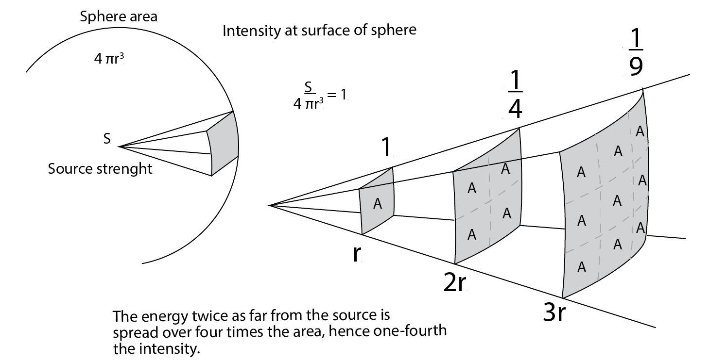
Consider a small lamp – effectively a point source of illumination – which emits a luminous flux F (lm) uniformly in all directions. Since the surface area of a sphere (which is  ) is proportional to the square of the radius, as the emitted radiation gets farther from the source, it is spread out over an area that increases in proportion to the square of the distance from the source. Hence, the intensity of radiation passing through any unit area (directly facing the point source) is inversely proportional to the square of the distance from the point source.
The luminous intensity I in any given direction is:  (lm/Sr or Cd). At a distance r from the source, this luminous flux will be projected onto an area A; at a distance 2r onto an area 4A and a distance 3r onto an area 9A. The illuminance then reduces with the square of the distance (
 ) from the source (as in the image below), so that
  .
.
Furthermore, if a receiving source is angularly displaced from the source, say by a zenith angle Z then the illuminance at our receiving point is determined by the following inverse square law:
(2) 
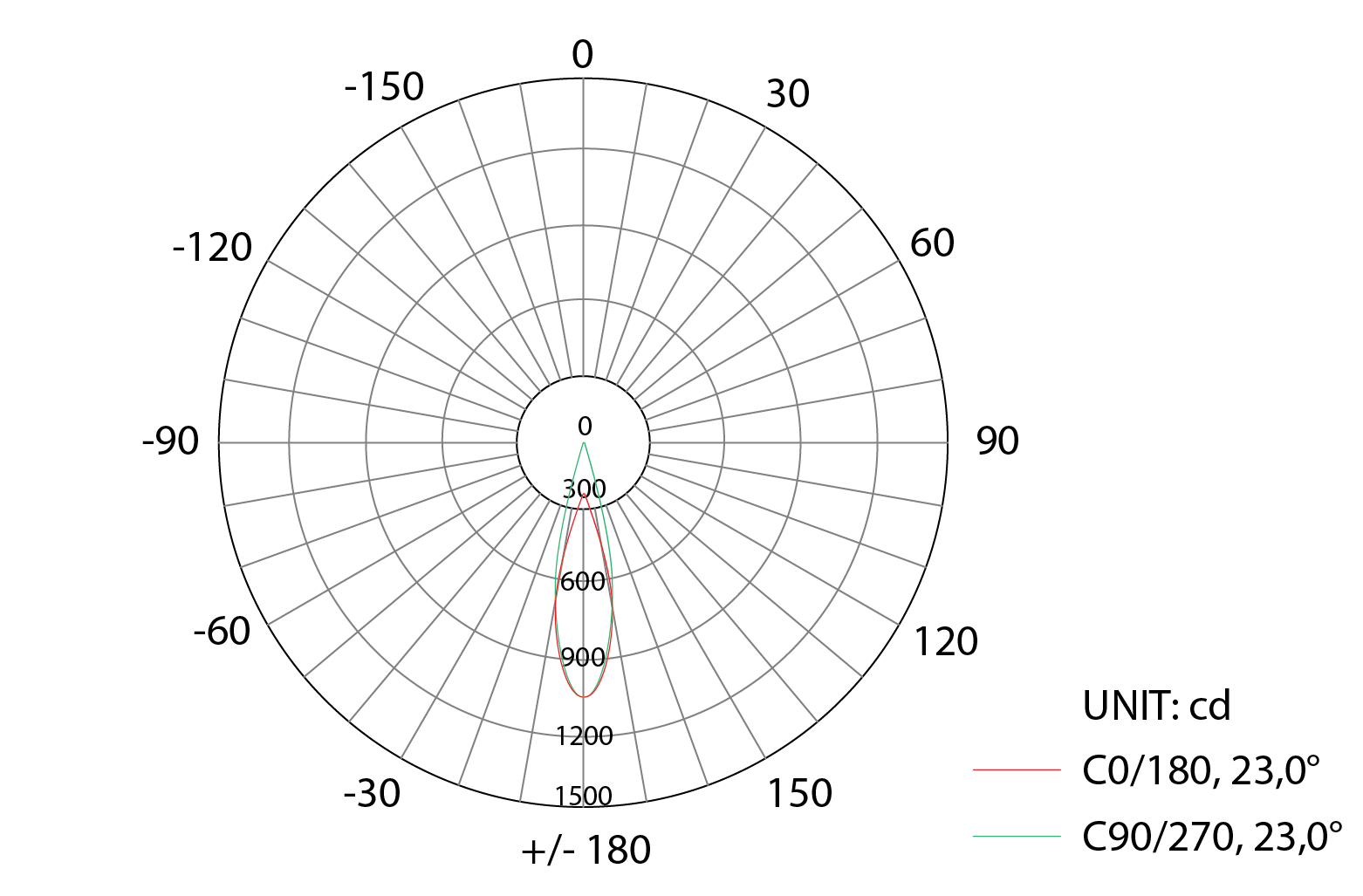
where r is the distance (m) from the point source of luminous flux. This though is a considerable simplification, since real lamps tend to be directional in their emission of light. See for example the polar plot below of the luminous intensity of an LED lamp. This reaches a peak of more than 1kCd directly beneath the lamp, but this quickly tails off at departures in either direction from below the lamp, reducing to almost half of the peak intensity at a departure of just 10o. For more realistic calculations of illuminance, this directionality does need to be addressed.
Of course in the interior of buildings, and in workplaces in particular, rooms tend to be illuminated by a regular array of light fittings. The number of light fittings n, arranged in a regular layout, that is required to meet a target average illuminance on the working plane  , is given by the following equation (this is commonly referred to as The Lumen Method):
(3) 
where A is the area of the room, assumed to be rectilinear[3] (so that the Area is the product of the room width w and length l), F is the luminous flux from the lamp,  is the number of lamps in each luminaire fitting,
  is a luminaire maintenance factor, typically having a value of around 0.8, to account for the accumulation of dirt on the surface of the lamp and luminaire fitting (thus reducing the emitted luminous flux), and
  is a utilisation factor. This latter, is normally provided by manufacturers as part of a lamps photometric data, as a function of a geometric index called the room index, k, and the reflectances of the room’s surfaces:
(4) 
in which, w and l are once again the room width and length, and h is the height at which the luminaire fitting is located above the working plane, typically assumed to be 0.8m above the floor. The utilisation factor thus accounts for the absorption of light emitted from the luminaires by the room’s bounding surfaces, so reducing the mean illuminance on the working plane.
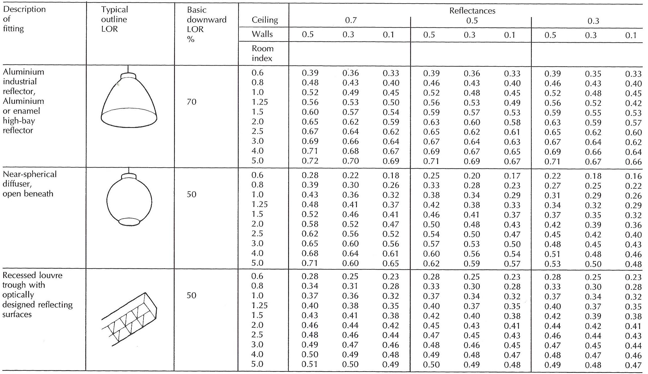
Shown below are examples of utilisation factor for different luminaires (discriminating by their downwards light output ratio – DLOR) as a function of room index and the reflectance of the walls and ceiling. The utilisation factors in this table vary by a factor of 4.5, from 0.16 to 0.72.
7.4 Lighting control
To minimise the demand for applied energy for lighting, artificial lights should only be fully activated when required to perform the tasks at hand. In other words whilst people are present – whether indoors or outdoors (unless lighting is for aesthetic purposes) – and whilst natural illumination is absent or insufficient. This then requires some form of lighting control.
The presence of an occupant in a room can be measured using a presence infrared (PIR) detector. This contains a sensor that measures changes in the temperature of surfaces that lie within the sensor’s field of view, these surfaces radiating heat to the sensor surface. When a person moves sufficiently within the sensor’s field of view a change in the absorbed radiant flux will be detected, indicating that a person’s presence is detected. This can be linked with one or more luminaires, so that these can be switched on and later switched off when a presence (strictly speaking, motion) has not been detected for a predefined time period. This can however result in situations whereby lights are switched off simply because someone has been immobile, such as when reading or working in front of a computer or indeed when their position is not within a sensor’s field of view.
The other principal type of sensor is a photosensor. These are normally solid-state devices which incorporate a photodiode which converts incident light into a photocurrent, the amount depending upon the magnitude of incident illumination. These are typically mounted on the underside of a luminaire, facing a floor or work surface and they can be calibrated to estimate the working plane illuminance based on the illuminance received at the sensor. A controller can then adjust the amount of light that is output from one or more luminaires to achieve the desired working plane illuminance, thus minimising the output of artificial light in the presence of daylight, with corresponding savings in electrical energy use.
Sophisticated lighting management systems can communicate with luminaire circuits throughout large and complex buildings, many of which may in turn integrate multiple instances of the above sensors as well as rudimentary time controls to ensure that lights switch on or off at predetermined times; while occupants are present and with their output dimmed in the presence of daylight. They may also of course be linked with fire detection systems to ensure that people are able to evacuate safely.
7.5 Questions and worked examples
This section contains a series of worked examples or problems (P) and their solutions (S), as well as a series of written questions (Q) and their written answers (A).
P1) A lamp emits a uniform luminous flux of 600 lm. What will be the illuminance at a point 3m distant from the lamp, at a zenith angle of 20o?
P2) The luminous intensity of an LED lamp at a zenith angle of 10o is 900 lm/Sr. What will be the illuminance at this angle, at a distance of 5m from the lamp?
P3) A rectangular office is 8m long and 5m wide. Its luminaires, each of which accommodates 2 lamps emitting a flux of 800 lm, are to be located at a height of 2.2m above the working plane. Given a maintenance factor of 0.8, a utilisation factor (corresponding to this lamp located in this room index) of 1.0 and a target mean illuminance of 500 Lux, how many lamps will be required?
P4) Assuming a layout of 3 rows of 5 luminaires, how should these be spaced across the width of our room?
S1) The mean luminous intensity ( ) is 48 lm/Sr. The illuminance at a distance of 3m and a zenith angle of 20o, using equation 2, is 5 Lux.
S2) The illuminance at 5m and a zenith angle of 10o from this lamp is 35.5 Lux.
S3) Using equation 3 above, we have (500 x 40)/(800 x 2 x 0.8 x 1) = 15.625. If we round this down to 15, this will allow for a convenient arrangement of 3 rows of 5 luminaires.
S4) Each row should be spaced a distance S from one another and a distance S/2 from the walls, so that we have  . Thus, each row should be spaced 1.67m from its adjacent row and the outermost rows should be positioned at 0.83m from the adjacent wall.
References
CIBSE (2015, updated 2021), Guide A: Environmental design, CIBSE.
McMullan R. (1998), Environmental Science in Building, 4th Ed, Macmillan.
Society of Lights and Lighting (2022), SLL Code for Lighting.
Further reading
Cayless, M.A. Marsden, A.M. (1983), Lamps and Lighting, 3rd Ed, Edward Arnold: London.
Pritchard, D.C. (1990) Lighting, 4th Ed, Longman scientific and technical.
- These are combined in their proportions as follows:
 ,
,  ,
,  ; so that
  and R, G, B are the total number of individual pixels in each colour channel ↵
 - The Society of Light and Lighting (SLL) Code for Lighting (SLL, 2022) recommends reflectances in the following ranges for the main diffusely reflecting interior surfaces: ceiling: 0.7 - 0.9; walls: 0.5 - 0.8 and floor: 0.2 - 0.6. ↵
- In principle, more complex room shapes can be accommodated, if these are broken down into individual rectangles ↵
